Laser straightness measurement with the Raspberry Pi
Introduction
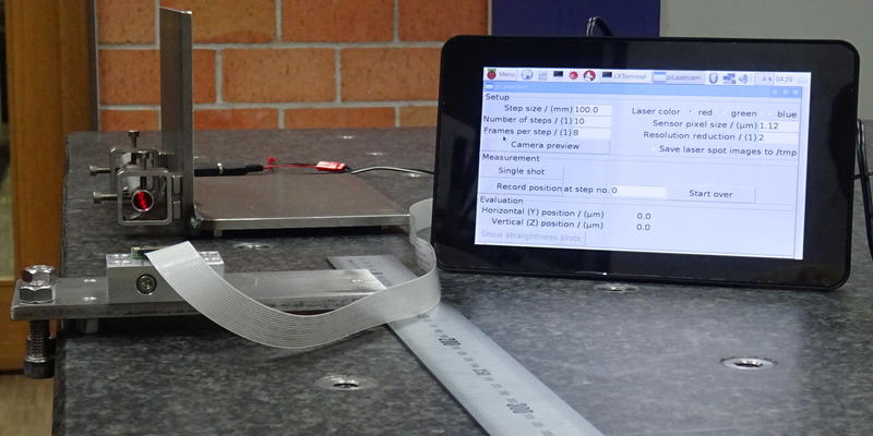
This page describes a homemade device for precise straightness and flatness measurement, e.g. for validating the accuracy of machine guideways or also surface plates. It uses a diode laser and the Raspberry Pi minicomputer with a modified PiCamera module. In my tests I achieved an accuracy of better than 5 µm over a length of 1 m using hardware components for only about 200 Euro.
In the following you will find all required background information to replicate the device including the software and links to hardware sellers.
The background: Why did I do this?
Several years ago I bought an used lathe which I am currently rebuilding. As the guideways are worn, my original plan was to remove the machine bed from the base and to take it to a machine shop for grinding. Finally I reconsidered that because
- it turned out that my favourite machine shop was not equipped to grind the guideway profile
- disassembling, transporting and reassembling the machine bed would have been a lot of work
- I accidentally came across a couple of youtube videos which showed the techniques for hand scraping, which is something I had long wanted to learn anyway.
However, scraping the machine bed by hand means an iterative process that involves frequent measurements until the desired shape is finally achieved. From scraping a first test part I estimated that it would probably take about 10 to 20 measurements to finish the bed with sufficient accuracy. So I was looking for a quick and easy way to measure the straightness, ideally both in horizontal and vertical direction at the same time.
Considering the alternatives: How to do it?
Possible methods for straightness measurement include:
- a precision ground reference bar which is placed directly above the machine bed. The measurement with a dial indicator would be quite easy to do, but the bar would need to be removed for every next scraping cycle.
- the rotational axis of a sufficiently stiff tube can be used as straightness reference when the tube is supported by ball bearings (or better: air bearings) at both ends. The tube can be lighter than a reference bar and thus is a bit easier to install and remove, but the measurement is more complex since the position of the rotational axis has to be calculated from the dial indicator value, the measured eccentricity of the tube, and the tube diameter.
- A steel or tungsten wire can also act as a straightness reference. Since the force of a dial indicator would bend the wire, the wire position must be measured by other means, e.g. with a microscope, capacitive probes, or by electrical contact to an adjustable tip (which in turn has a dial indicator on top of it). No idea how accurate this is, but it is definitely not even as quick as with the reference bar.
- an optical (and quite precise) measurement can be done with an autocollimator. This method works simultaneously in both directions. However autocollimators are expensive, and the only one I currently have access to is incomplete.
- at my workplace we have an interferometer which can be used for straightness measurement together with a Wollaston prism. While this is quite accurate, setting up the equipment takes time, horizontal and vertical measurements have to be taken separately, the boxes with all the equipment are huge... and the lathe is >300 km away from my workplace.
- the combination of a laser and a PSD (position sensitive device). The stationary laser illuminates the PSD which is moved along the guideway and detects the position of the laser spot simultaneously in both directions. This is a quite elegant and also quite precise method, since the straightness of the laser beam is directly used as reference (still, when looking closely enough, even a laser beam may not be perfectly straight, but more on this below).
After some contemplation it occurred to me that the same measurement principle as with the PSD could be replicated with a webcam and a laserpointer. A quick internet search revealed that the Raspberry Pi would be the ideal platform for this project, not only because I already had one, but also because there is a camera module available which offers easy access to all its optical components. Due to the small pixel size of the camera chip (1.12 µm in case of the v2 camera), it should theoretically be possible to detect the center of the laser spot with nanometer resolution, using hardware for just a few hundred Euro in total. All this was just too tempting, so I had to do it...
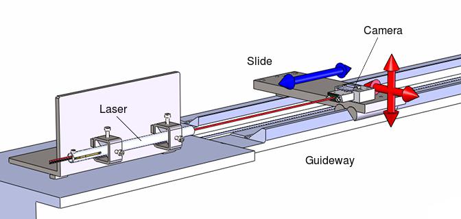
Measurement principle: The stationary laser is aligned parallel to the guideway and projects a spot on the chip of a camera. As the camera slide is moved along the guideway step by step (blue arrow), straightness errors cause a lateral shift (red arrows) which is measured by detecting the position of the laser spot on the camera chip.
Small alignment errors between laser and guideway cause a steady increase of the lateral shift with each step and can be automatically eliminated from the result.
Putting everything together
The projected measurement device consists of several elements:
- camera with a stable mount to place it on the guideway
- beam filter to dim the intensity of the laser to a level which is safe for the camera chip (a sufficiently dark filter also blocks almost all ambient light, so the measurement can be done under normal lighting conditions)
- laser with adjustable stand to align it (roughly) parallel to the guideway
- Raspberry Pi with the necessary software to capture the images of the laser spot and to calculate the position of the laser spot
The software, as well as drawings of all relevant parts, can be downloaded via the links at the bottom of this page.
Camera
When I received the camera module, I discovered that the sensor sits on a small separate chip that is attached to the PCB with elastic glue. Since a sufficiently accurate measurement requires a defined lateral position of the sensor relative to the guideway, this seemed not really optimal.
I decided to remove the sensor from the board (the elastic glue can be cut with a razor and wiped off with acetone) and to glue it to an aluminum block with epoxy resin. The block has a couple of mounting holes to attach it to a slide with which it can then be placed on the guideway. Bending the sensor away from the PCB by 90 degrees feels a bit critical due to the rather stiff cable, but makes it possible to place the sensor close to the guideway without getting in conflict with the cable outlet on the PCB.
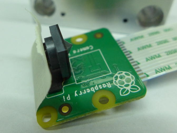
Camera module after removing the elastic glue between sensor and PCB, immediately before gluing to the aluminum block (the grey cone on the sensor is epoxy resin). The tape on the camera lens prevents the sensor from bending back towards the PCB.
In its original state (with lens attached) the camera distinguishes different angles of the incoming light. Parallel beams (as long as they hit the camera lens) are always focused on the same pixel on the sensor. This application requires the opposite: The sensor should detect a lateral movement of the camera relative to the laser beam while being insensitive to (small) angular deviations of the camera. This can easily be achieved by removing the camera lens. It is secured with some drops of glue and can be unscrewed quite easily.
Since now the beam is not focused any more, it illuminates a sensor area as large as the beam diameter (around 1 to 3 mm for common diode lasers). A precise measurement can only be achieved if the center of the beam can be accurately detected. This is unavoidable and a central challenge of this measurement principle.
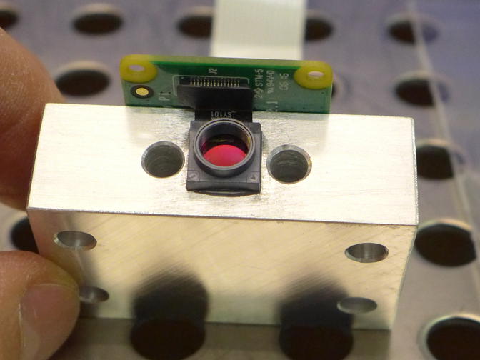
Camera after removing the lens. Obviously the time in which the camera chip is exposed to the dusty ambient air before mounting the filter should be kept minimal.
Beam filter
To sufficiently dim the laser intensity my first approach was to use the safety film from a pair of old solar eclipse glasses. As it turned out, in combination with a green 1 mW (class 1) laserpointer the amount of light reduction is just right to get a reasonable exposure speed.
However, I had never been too happy with the optical quality of that pair of glasses, and the image of the laser spot revealed lots of local irregularities which severely distort the laser spot and thus make this kind of film unuseable for a sufficiently precise measurement (compare the following images).
The Baader AstroSolar film works much better, but even with this high quality material I found single local defects in the coating which cause variations in the shape of the laser spot.
Finally I switched over to welding safety filters. In the version without reflective coating they consist of glass with uniform opacity and thus do not show local defects. Additionally they are available in different grades of opacity which makes it possible to fine-tune the laser intensity on the sensor. While my green class 1 laserpointer requires at least a class 12 safety glass (according to DIN EN 166), a class 10 glass was sufficient in combination with a red class 1 laser module.
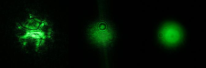
Laser spot of a 1 mW DPSS laserpointer behind different intensity filters. Left: no-name solar safety film, middle: Baader AstroSolar film (image taken at a local defect), right: Uncoated welding safety glass. The small concentric circles are caused by scattering at dust particles on the filter.
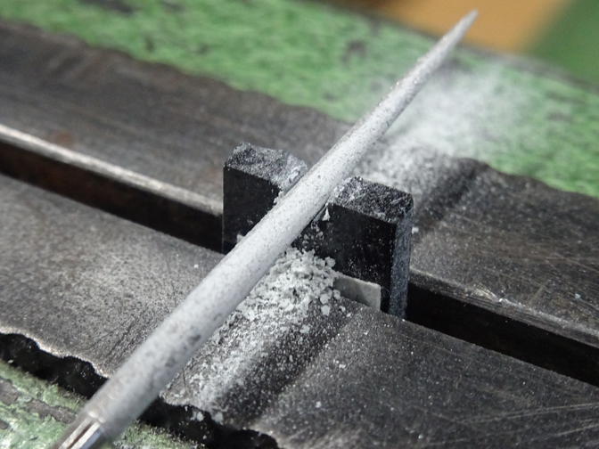
Shaping the filter glass with a diamond file. The center portion of the glass is covered with tape to avoid scratches.
To avoid interference and ghost images that might occur when the laser is reflected back and forth between sensor and beam filter, the filter is mounted in tilted orientation at a sufficient distance to the sensor. Additionally the center bore in the filter mount is threaded to absorb as much scattered light as possible.
The annular gap between camera and filter mount is sealed with an O-ring (7.0 x 1.0) to protect the chip from dust. In contrast to the situation with camera lenses, also the filter itself should be kept very clean, since the parallel laser light directly projects dust particles from the filter to the chip (and, due to the necessary distance in between, also adds scattering effects).
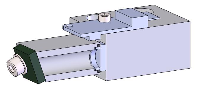
Cutaway view of the camera unit with beam filter. Note the O-ring between filter mount and camera chip. The screws holding the filter have nylon washers to protect the glass.
As the experiments revealed, the sensitivity to dust particles is a major downside of using a filter mount in the depicted configuration. Due to the rather large distance between filter and camera chip, light which is scattered at a dust particle on the filter spreads over a considerably large circular area of the spot image.
Furthermore, in my early experiments I observed a fine granularity of the laser spot (as seen in
this image), which I thought was caused by small inhomogeneities of the filter glass. However, as I removed the glass some time later, I discovered that actually some oily dew had built up on the inner surface of the filter. Although I have no definitive explanation for this, I suppose that some coolant from machining survived the cleaning in the inner thread of the filter mount, where it was evaporated by the warm camera chip and finally condensed on the cooler filter glass.
Since the filter mount is also quite expensive to manufacture, a more pragmatic (however less flexible) approach would be to glue a small piece of filter glass on (or directly into) the lens mount of the camera and to omit the filter mount completely. In the meantime I have bought another camera module and modified it this way. There are some interference effects due to the glass surfaces being not exactly parallel, but basically the camera seems to work similarly well as the first one. I will update this page once I have gained more practical experience.
Laser
Choosing a laser which is suitable for an accurate measurement is not an easy task, since the overall performance depends on a number of properties that are normally not part of the datasheet (at least not in case of cheap laser modules). These include:
- symmetric shape of the laser spot (ideally round with Gaussian intensity distribution)
- good collimation and low beam divergence (low distance dependency of spot size, spot shape and intensity distribution)
- long-term stability of the beam direction
Basically there are two affordable options, each with its pros and cons:
- Diode lasers are available in many different wavelengths from infrared to (ultra)violet, with the most "traditional" type being the red 670 nm laser. They generate only negligible waste heat, so thermal distortion is usually minimal which results in a steady beam direction. On the other hand, normal laser diodes emit the light on a rectangular surface which normally results in an asymmetric spot.
- Diode pumped solid state (DPSS) lasers generate their light by doubling the frequency of a infrared laser diode, which is a quite inefficient process that creates noticeable waste heat. This waste heat causes thermal distortion of the laser components, which will usually make it necessary to install a cooling and to wait for several minutes after powering on until the beam direction has stabilized. On the positive side, DPSS lasers normally have a much better spot symmetry and lower beam divergence than diode lasers. The most common type are green lasers with 532 nm wavelength.
At the beginning of this project I was not sure how big the impact of each of these properties on the resulting measurement accuracy would be, so I decided to continue with both laser types. The following graphs were created with an early version of my straightness measurement software and show a comparison of a red diode laser and a green DPSS laser regarding the stability of the beam direction. The image below shows the laser spot of these two lasers in different distances from the camera.
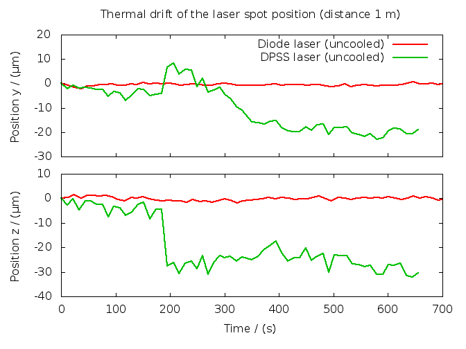
Thermal drift of the spot position of a red diode laser and a green DPSS laser pointer in 1 m distance to the camera. At the beginning of the measurement the DPSS laser was already switched on for several minutes. While the beam direction of the red diode laser remains very stable, the DPSS laser shows not only a gradual drift, but also short-term fluctuations and sudden "jumps" of the beam, probably caused by some internal elements sliding across each other after sufficient thermal stress has built up. As the beam direction needs to be stable (or at least predictable) during a straightness measurement, these effects greatly reduce the achievable accuracy.
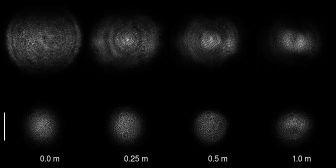
Camera images of the laser spot from a red diode laser (above) and a green DPSS laser (below) in different distances from the laser. The height of the white bar near the lower left corner equals 1 mm.
As I discovered later, the pixel-sized granularity was caused by a fine layer of oily dew on the inner surface of the beam filter.
So far, the results were quite unsatisfying. While the DPSS laser limits the accuracy due to its unstable beam direction, the asymmetric spot of the diode laser makes a precise detection of the spot center more difficult. At this point I was beginning to accept that I had reached the limit of this simple low-cost approach and that optimum accuracy would probably require a really expensive laser source. However, before I could find the time to actually quantify the influence of the beam asymmetry, bad luck came to my rescue...
Searching for diode lasers with low divergence, uniform intensity distribution and sufficiently small beam diameter, I came across the Quarton VLM650-11-LPT module which had very promising specs so I ordered one immediately. After I had received it, it turned out that there had been an error in the datasheet and that the actual beam diameter was somewhere around 5 to 6 mm. As this is even bigger than the camera chip, the module seemed clearly unusable.
However, shortly before returning it to the dealer it occurred to me that it might still be possible to use this module if a baffle was added to reduce the beam diameter. After some experimenting I found that this results in an almost perfectly symmetric beam. Regardless of the obvious beam divergence and diffraction effects I now had a laser source with excellent properties for this task.
As I found out, there are several noteworthy aspects about designing the baffle:
- Obviously, the hole in the baffle should be free of burrs and as round as possible. A thin baffle (about 1 mm or less) avoids undesirable effects if the baffle is not perfectly perpendicular to the beam.
- As the beam direction of many laser modules may be quite different from the center axis of their housing, it is beneficial to mount the baffle close to the laser module to cut out the center of the emitted beam which is probably most uniform in its intensity.
- Due to diffraction effects the intensity distribution of the beam is not yet smooth in a close distance behind the baffle. The smaller the baffle, the shorter is the distance which it takes for the beam to "settle". However, due to some inconvenient laws of physics, achieving a small spot size and a low beam divergence are conflicting goals. This seems to have the effect that in a large distance from the laser the beam diameter may be bigger with a small baffle than with a bigger one. In my experiments with a 1.0 mm and 1.5 mm baffle this was the case at distances greater than about 3 to 4 m.
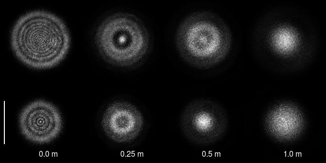
Camera images of the laser spot from a red diode laser (VLM650-11-LPT) with a 1.5 mm baffle (above) and 1 mm baffle (below) in different distances from the laser. Although the intensity distribution looks quite different depending on the distance, it always remains very symmetric which allows a precise detection of the spot center. The height of the white bar near the lower left corner equals 1 mm.
As I originally ordered the Quarton module by accident, it may or may not be the optimum choice here. If you are planning to use a baffle from the very beginning, there may be other laser modules which are even more suitable.
Due to the very low beam divergence and nice symmetry of my green DPSS laser pointer, I decided to also buy a DPSS laser module and to fit it with a cooling fan for faster thermal settling. However it turned out that this module has a disappointingly elliptical beam exiting it at a large angle to the housing center axis which even made mounting it difficult. So for now I stay with the red laser module/baffle combination which I mounted into a 200 mm long aluminum tube to make aligning the beam direction to the guideway easier.
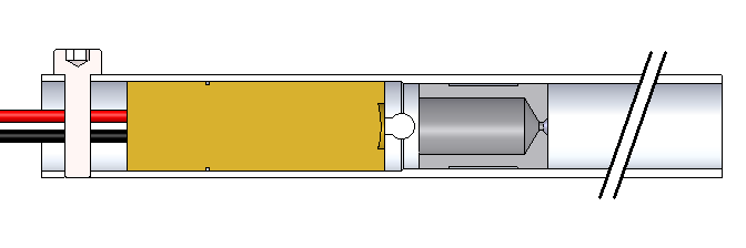
Cross section of the laser unit. The laser module (brass-colored) is clamped in the slotted end of the aluminum tube (placing a screw into such a short aluminum thread is not really nice, but to avoid deforming the tube it should not be firmly tightened anyway). The black plastic baffle is press-fitted.
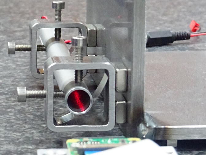
The laser mount allows both lateral and angular adjustment of the beam. Coarse alignment is done by moving the square-tube/magnet elements (or the complete L steel base), while fine alignment is done with the adjustment screws. The laser tube is held in place by 0.15 mm spring steel plates which were not cut to length, but broken by bending them very tightly. This results in curved ends which can glide inside the square tube more smoothly.
The most efficient approach for aligning is to place the camera close to the laser to adjust the laser laterally, then to place the camera at farthest distance from the laser to adjust the laser angle. This usually needs to be done iteratively several times until the complete laser spot remains within the field of view of the camera along the whole travel.
Raspberry Pi with software
The hardware platform used is a standard Raspberry Pi B+ with camera module v. 2.1. For better handling the Raspberry was equipped with a touchscreen display and installed in a housing.
In the out-of-the-box configuration, the Pi is not yet ready for straightness measurement. The following changes are required (or at least recommended):
- For use with the v2 camera module you need at least version 8 of Raspbian (codename Jessie). If in doubt, check the content of the file /etc/debian_version and upgrade the OS if necessary.
- Enable the camera: start raspi-config (type sudo raspi-config in a terminal window), select "Enable Camera" and hit the Enter key.
If the camera was sucessfully activated, the terminal command
vcgencmd get_camera
should output supported=1 detected=1. Now you should be able to take images by typing
raspistill -o test.jpg - For saving images with native resolution, the GPU needs 256 MB of memory. This can be set in raspi-config under "Advanced Options" -> "Memory Split".
- Start the package manager (sudo aptitude) and make sure the packages "python-scipy" and "python-matplotlib" are installed.
- If you intend to use the Pi with touchscreen:
- Install a virtual keyboard. Matchbox-keyboard is frequently recommended for the Raspberry, however in my case it caused the file manager to consume 100% CPU (even after exiting Matchbox-keyboard). Florence, on the other hand, often gave me double or triple letters for one single keystroke (only after I had installed additional packages to keep it from crashing immediately). I ended up with using xvkbd, which does not readily integrate with the start menu, but works flawlessly. A sample desktop icon for starting xvkbd (to be saved to /home/pi/Desktop) can be downloaded
here. Xvkbd can be configured in several ways (see its manual page); one of the easiest is to create a resources file /home/pi/XVkbd (as always, file names are case sensitive). For example, to make xvkbd start with a German layout and without keypad, this file could contain the lines
xvkbd.customization: -german
xvkbd.keypad: false - If you use the Official 7" Touchscreen together with the Official Touchscreen Case, you need to rotate the screen by 180 degrees. Edit the config file (sudo nano /boot/config.txt) and add a line
lcd_rotate=2
(The more frequently recommended option is display_rotate=2, however this rotates only the display output and leaves the touchscreen input unchanged. Try this if you want the handling to be a little more challenging.) - To make the touchscreen accept slower double-clicks which do not precisely hit the same spot twice, edit (or, as in my case, create) the file /home/pi/.gtkrc-2.0 with the lines
gtk-double-click-time=500
gtk-double-click-distance=10 - You may also want to reduce the backlight brightness. Valid values range from 0 to 255; for example:
sudo su
echo "96" > /sys/class/backlight/rpi_backlight/brightness
- Install a virtual keyboard. Matchbox-keyboard is frequently recommended for the Raspberry, however in my case it caused the file manager to consume 100% CPU (even after exiting Matchbox-keyboard). Florence, on the other hand, often gave me double or triple letters for one single keystroke (only after I had installed additional packages to keep it from crashing immediately). I ended up with using xvkbd, which does not readily integrate with the start menu, but works flawlessly. A sample desktop icon for starting xvkbd (to be saved to /home/pi/Desktop) can be downloaded
here. Xvkbd can be configured in several ways (see its manual page); one of the easiest is to create a resources file /home/pi/XVkbd (as always, file names are case sensitive). For example, to make xvkbd start with a German layout and without keypad, this file could contain the lines
piLasercam
The straightness measurement software "piLasercam" is written in Python and has the following main features:
- preview of the camera image to align the laser (roughly) parallel to the guideway
- "single shot" measurement to get the current position of the spot center on the sensor
- measurement cycle (the actual straightness measurement during which the camera is moved along the guideway step by step)
- display of straightness graphs in Y and Z direction (when a measurement cycle has been completed)
- output of a logfile to the folder piLasercam in the home directory for later reference
As with many straightness measurement principles, the whole travel is divided in a user-defineable number of steps and one measurement is taken at each of these steps. When preparing the measurement, the laser needs to be aligned parallel to the guideway so that the complete laser spot hits the camera sensor along the whole travel. While a good alignment is beneficial for a couple of reasons (see below), the alignment need not be perfect: piLasercam calculates the linear offset caused by the laser misalignment and subtracts it from the measurements when creating the straightness graphs.
For displaying the results a right-hand coordinate system is used. The guideway direction is defined as the X-axis with increasing X values in increasing distance from the laser. The Y-axis is parallel to the longer edge of the camera sensor (normally this is the direction of the horizontal deviation). The Z-axis is parallel to the shorter edge of the camera sensor (normally in direction of the vertical deviation).
The single parameters and the handling of piLasercam is now explained in detail:
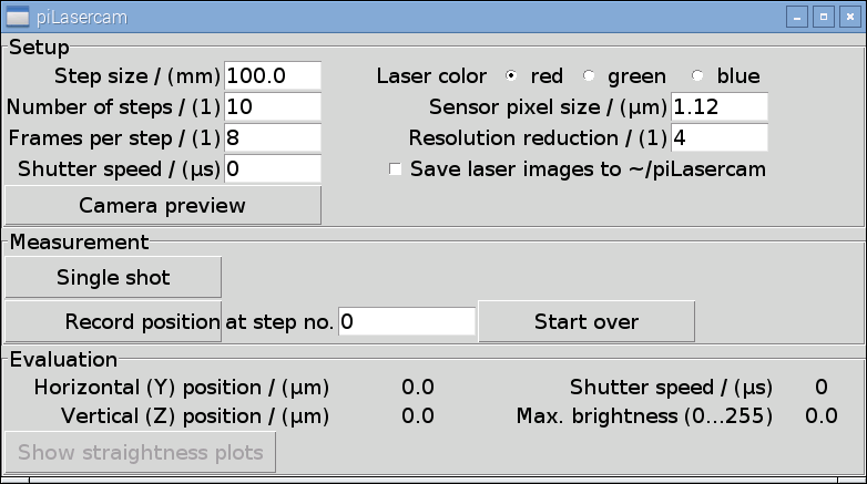
Screenshot of piLasercam with default settings. The font was chosen rather large to be more touchscreen-friendly.
Setup
- Step size / (mm)
- The distance by which the camera is moved along the guideway between each single measurement.
- Number of steps / (1)
- During a complete measurement cycle the camera is moved away from the laser this many times. The starting position (closest to the laser) is step number 0, so a measurement cycle with 10 steps contains 11 measured points.
- Frames per step / (1)
- When looking closely enough even a laser beam is not exactly straight. Instead, perturbations of the ambient air can cause an unsteadiness of the beam by several microns per meter. For values greater than 1, piLasercam will average this many frames (images of the laser spot) to achieve a more accurate mean spot position.
- Shutter speed / (µs)
- For accurate detection of the laser spot center, the value of the brightest pixel (shown in the label Evaluation -> Max. brightness) should always be considerably below 255. If auto exposure (the default if Shutter speed = 0) delivers insufficient results, this option can be used to adjust the brightness manually. In combination with a suitable beam filter, usual values range from about 5000 to 100000.
- Laser color
- To achieve optimum signal to noise ratio, only one of the three color channels of the camera is evaluated. This should be set to the color which matches the laser color.
- Sensor pixel size / (µm)
- This value is important for converting the detected spot position from pixels to micrometers. The default (1.12 µm) is the pixel size of the v2 camera chip.
- Resolution reduction / (1)
- Lowering the resolution of the camera images also lowers the CPU and memory requirements. If this value is e.g. set to 4, an area of 4x4 physical pixels is recorded as one image pixel, i.e. the recorded image has only 1/16 of the native pixel count. This will considerably speed up the image processing while still maintaining good accuracy, so 4 is the default value here. A value of 1 (full camera resolution) is not possible with the Raspberry Pi B+ due to hardware limitations.
Both width and height of the full camera resolution must be dividable by the value you set here. For the v2 camera chip, the values 2, 4, 8 and 16 are possible. - Save laser images to ~/piLasercam
- In addition to the logfile which is saved to ~/piLasercam/plc_[year]-[month]-[day].log, this checkbox allows you to also save the images of the laser spot to the same directory. For each measurement piLasercam will save the raw image as plc_[timestamp]_raw.png and the processed image (after intensity correction) as plc_[timestamp]_intensity_[spot position y in pixels],[spot position z in pixels].png. The timestamp in the filename is identical to the timestamp in the logfile.
- Camera preview
- Pressing this button enables a live view of the camera for aligning the laser parallel to the guideway. The preview is semi-transparent so it allows you to still use the mouse cursor. Before taking a measurement the preview needs to be closed.
Measurement
- Single shot
- Starts one single measurement of the laser spot position. This can be used e.g. for analyzing the stability of the laser beam direction by repeatedly taking single shots with the same distance between camera and laser during a certain period of time.
- Record position at step no. ...
- Starts one measurement of the actual straightness measurement cycle. The step number is automatically counted forward after one step has been completed. The counter will stop when the last step of the cycle has been reached. In case something went wrong during a measurement cycle, it is possible to manually change the step number and to take a new measurement for this step even after subsequent steps were already measured. It is also possible to take an additional single shot measurement while recording a measurement cycle.
- Start over
- Deletes the position values already recorded during previous measurement cycles and sets the position counter back to zero.
Evaluation
- Horizontal (Y) position / (µm), Vertical (Z) position / (µm)
- The detected position of the laser spot center relative to the upper left corner of the camera sensor.
- Shutter speed / (µs)
- This label shows the actual shutter speed that was used by the camera (as opposed to the desired shutter speed entered in the corresponding setup entry above).
- Max. brightness (0...255)
- The brightness of the brightest pixel in the laser spot image. For a precise measurement, the value should be somewhere around 150 to 220. Especially if you get larger values close or even equal to to 255, it is recommended to set the shutter speed manually.
- Show straightness plots
- This button opens a new window displaying the straightness graphs in Y and Z direction. It is enabled when a measurement cycle is completed. If the graph window is still open from a previous measurement cycle, pressing the button displays the result of the current measurement in addition to the previous graphs. The graphs can be zoomed and saved to a file using the buttons at the lower edge of the window.
Under the hood
The core functionality of piLasercam is the precise detection of the laser spot center. For those who are interested, here is some background information on the implemented approach:
- First, the color channel which provides the best signal/noise ratio is extracted from the image (user selectable: red, green or blue, whichever corresponds best to the wavelength of the laser).
- If several frames per step are captured (the default), their brightness values are averaged.
- If necessary, an average of the background noise is subtracted from the image. For directly capturing to a numerical array in memory as is used here, it appears the camera library already does this automatically, so this step is usually skipped.
- The numerical brightness values are fed into a correction function. The resulting values are (approximately) proportional to the light intensity.
The required function for calculating the actual intensity was found by taking several pictures of the laser spot with varying shutter speed. As expected, the results show that with increasing absolute intensity, the camera becomes less sensitive to a certain intensity step. This is beneficial for usual imaging, since it translates as much dynamic range as possible into image information.
For the current application, this nonlinear behaviour of the camera needs to be compensated. The software uses an exponential function to approximately linearize intensity and pixel brightness (compare the graph below). The coefficients of the function were determined experimentally. - The center of the laser spot (i.e. the center of gravity of the intensity distribution) is calculated: the intensity value of each pixel corresponds to its "weight". The weight of each pixel, multiplied by its distance to the image origin, corresponds to its "torque". The sum of all torques divided by the sum of all weights is the distance between the image origin and the center of gravity, i.e. the center of the laser spot.
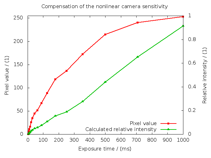
Dependency between light intensity input (exposure time) and pixel value of the camera output before (red) and after (green) applying an exponential correction function.
Tips and tricks (or: how to minimize errors)
The experiments revealed a number of factors which can heavily influence the accuracy of the measurement. The most important ones (or at least these which I could identify as such) are now discussed in detail.
Laser beam quality
Although you may get quite reproducible results when repeating a measurement several times, they may still contain a large total error due to distance-dependent beam asymmetry and uneven intensity distribution. An easy way to identify at least most of this error is to take two subsequent measurements and to rotate the laser around its axis by 180° in between (also point the laser to a slightly different spot on the sensor so you don't hit the same dust particles twice).
Air flow
When looking closely enough, even a laser beam is not exactly straight. Instead, perturbations of the ambient air cause an unsteadiness of the beam by several microns per meter. To get an idea about the magnitude of this influence, place the camera at maximum distance to the laser and take a couple of single shots.
These errors can be minimized by:
- Measuring in a steady environment with constant temperature and no open windows etc.
- Shielding the light path with e.g. some sheets of roof-shaped folded paper (also take care not to breathe into the light path during the measurement).
- Increasing the number of "Frames per step" to average more images of the spot to eventually achieve a more accurate mean spot position after a couple of seconds.
Inaccurate step size
Normally, guideway and laser direction will not be perfectly aligned, so piLasercam defines the first and the last measured position as reference points with zero straightness error. However, this requires uniform distance steps between all single measurement points. As the laser spot moves across the camera chip when the camera is moved away from the laser, there is no way to separate actual straightness errors from errors caused by the camera standing in the wrong distance from the laser. Put in other words, the better the beam alignment, the lower is the influence from an inaccurate step size.
Sensor nonlinearity
As already described, the brightness value of a pixel is connected to the incoming intensity in a nonlinear way. With increasing total brightness, the camera requires a greater light intensity step for an output pixel to reach the next higher pixel value. Although the nonlinearity is approximately compensated with the correction function mentioned above, this results in a larger compensation error and also a lower intensity resolution compared to a pixel with medium brightness. This is basically the reason why large brightness values should be avoided.
Sensor and filter characteristics
Light scattered by dust particles on the beam filter affects the intensity distribution on the chip. In combination with a distance-dependent beam shape and inaccurate beam alignment this causes errors which cannot be completely eliminated. Additionally, single pixels may appear as bright "hotpixels" especially under low-light conditions. Also for these reasons it is beneficial to align the beam as precisely as possible to the guideway so that the laser spot always hits the same portion of the filter and of the chip.
Results
To validate the measurement accuracy I used a precise granite surface plate at my workplace. Due to some special requirements we have there, also one of the side surfaces has a specified flatness, so the plate has one edge which is straight in both directions.
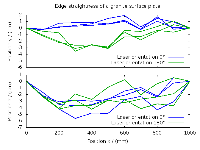
Straightness results measured with the setup shown in the intro image. After taking three measurements the laser was rotated around its axis by 180°. Measurements were taken with 8 frames per step, resolution reduction 2, without shielding the light path. The lower repeatability in z direction is most probably caused by the flow of the air condition which hits the granite directly from above.
According to the calibration document, the straightness of the surface plate should be better than 1 µm in both directions, however it is quite likely that there has been some wear in the meantime. Considering that the graphs contain both the errors of my setup and of the surface plate itself, a measured straightness of less than 5 µm in both directions seems like a quite satisfying result.
As can be seen especially in the graph of the y straightness, the repeatability is noticeably better than the absolute accuracy. This indicates systematic errors (in this specific case my main assumption is a remaining beam asymmetry), the elimination of which would lead to a further accuracy improvement. For reworking my lathe the system is already better than I need it, but since I know now that there is still something left to improve, I will likely revisit this topic some time in the future.
Links and sources
Hardware: commercially available parts
Of course the parts listed here are available in numerous stores around the world. Just as a starting point, these are the places where I got mine:
- Reichelt Elektronik
- Raspberry Pi B+, SD-card with Raspbian OS, power supply
- ELV Elektronik
- Raspberry Pi Touchscreen-Display 7", Raspberry camera module v2.1, 75 cm camera cable
- The Pi Hut (ordered via Amazon.com)
- Raspberry Pi Official Touchscreen Case
- Schweisstechnik Raithel
- Welding safety glass Aulektro 10 FW 1 (for use with a red 1 mW laser module). In combination with a green 1 mW laser you will need a darker glass (about 13 FW 1).
- Roithner Lasertechnik
- Laser module VLM650-11-LPT (manufactured by Quarton)
- Supermagnete
- Neodymium magnets Q-20-10-05-N for fastening the laser adjustment frames on the angle steel base. The angle steel has three more magnets as feet.
Hardware: technical drawings for custom-made parts
Camera: base
Camera: filter mount
Camera: filter
Laser: aluminum tube
Laser: baffle
Laser mount: base element
Laser mount: adjustment frame
Software
- piLasercam.py (version 0.1, 2018-02-28)
- Straightness measurement software (to be saved wherever you want to find it, e.g. to /home/pi/software). If you want to keep everything in one place, the logfile directory /home/pi/piLasercam is also a safe choice.
- piLasercam.desktop
- Desktop shortcut for piLasercam (to be saved to /home/pi/Desktop). Edit the file to make sure it points to the directory where you keep piLasercam.py
- xvkbd.desktop
- Desktop shortcut for xvkbd (to be saved to /home/pi/Desktop).
Credits
Very special thanks to CNC-Technik Ender for machining the necessary parts with great quality and in almost no time.
this page last updated 2018-03-02